Various changes, modifications and equivalents in addition to those shown or described will become apparent to those skilled in the art and are similarly intended to fall within the spirit and scope of the invention whether or not they presently exist in the following claims or are later made in amended claims. Terms of Use 11 is a cross sectional profile view of the antenna mast system 100 with mast sections #1 and #2 in fully deployed positions Lie and L2b with lifting pin 206 in an inserted and locked position, and with lifting cylinder rod 203 fully retracted and with bottom holding latches in locked positions. [0045] FIG. [0021] FIG. 7. 10A for detail O of FIG. Mast section ears 10a, b of mast section #3 rest on the surface of upper flange 14 of mast section #4. Mast section #3 is further equipped with four set of predefined slots in its structural perimeter. At full height this unit can withstand 45 mph winds. / 34.29 cm through 5.25 in. Delivering the hydraulic telescopic mast system as an option, Hilomast is proud to supply these products to the market. For extra stability four retractable outriggers can be extended in a flat horizontal configuration measuring 19` x 18`. / 13.34 cm, Elevates heavier loads with greater wind sail area, Shorter guy radius support requires less space, Lower nested height eliminates the need for costly and complicated tilt systems, Lightweight design allows for more COW and COLT payload space, Safe long-term deployment with easy to operate positive locking pins, Designed and manufactured in the USA by the portable elevation experts . | when lifting cylinder rod 203 in fully retracted, rest position. Please feel free to contact Hilomast from our Contact page of this website, or call Hilomast, (386) 221-5006, and we will be glad to discuss details and/or options relating to your specific needs or on other competitive products in which we specialize. 205a,b in contact with holding slots 21a, b, thereby maintaining mast section #1 in its vertical position. Third from the top slots 27a, b of mast section #3 are used for insertion and removal of mast section #4 insertable lifting pin 208. ORIGINAL CODE: 0009012, Kind code of ref document: [0063] FIG.
Constrained The nested height of 11.3 feet (3.4 m) eliminates the need for a tilt system, delivering cost savings, reducing complexity and allowing for more payload capacity on a COW or COLT. Since mast section #2 has been elevated to the maximum allowable elevation L2a, the holding latches 205a, b are set to latch when mast section #2 is lowered slightly using lifting cylinder rod 203, from the maximum allowable elevation L2a to holding latch slot alignment position L2b shown in FIG. These hydraulic telescopic mast are innovatively designed for powerful signal transduction that ensures the smooth connection between people through different communication devices. 1.5.15 Continue moving lifting cylinder rod 203 upwardly, after making contact with the bottom surface 33 of third lifting pin 207, until upper surface 30 of the third lifting pin 207 comes in contact with upper portion of cutouts 26a, b, thereby lifting mast sections #3 and sections #l-#2 together. 1.3 Attach antenna or other load equipment to the top of mast section #1. Constructed of steel and lightweight aluminum the unit is supported by four retractable outriggers for extra stability during operation. Mast section #5 is not provided with a set of vertical travel limit ears since there is no vertical movement of mast section #5 associated with the telescoping of the stack. When lifting cylinder rod 203 is in contact with the bottom surface 7 of the lifting pin 6, the bottom holding latches 205a,b are released to allow free vertical movement of the mast section #1 that is being elevated by the vertical displacement of the lifting cylinder rod 203. When fully deployed the tower extends to 30 feet with a base measurement of 7` x 6` (without outriggers). 3 is a cross sectional profile view of the antenna mast system 100 in a fully retracted (stowed) configuration. [0002] Prior art antenna masts are either operated by hydraulic or by mechanical crank operated drive means which are frequently employed in combination with bulky framework structures providing the required support. HYDRAULIC TELESCOPIC ANTENNA MAST SYSTEM AND METHOD FOR. FIG. Mast section #1 is the inner most of the sections and consequently has the smallest overall cross section. 402 Chairman Court, Suite 100 [0027] FIG. The antenna mast of Claim 3 wherein each of the one or more lifting pins of the one or more upper mast sections except for the one or more lifting pins of the topmost one of the upper mast portions is a retractable lifting pin. Compared to hydraulic steel masts, it delivers higher lifting capacity at a lower weight of 880 pounds (399 kg). 1.5.1 1 Upon alignment of the bottom cutout 22a, b of the second mast section #2 and upper cutouts 18a, b; 19a, b; 20a, b of mast sections #3-#5, extend. 5 A for detail F of FIG. 6A is a cross sectional detailing initial deployment mode configuration with the hydraulic ram in contact with lifting rod of the first mast section. 1.5.24 Retract lifting cylinder rod 203 to a rest position (wherein combined mast sections #l-#4 are fully extended and supported by locking latches 205a, b). In a stowed or retracted configuration, mast section #4 vertical travel limit ears (1 la, b) rest on mast section #5 upper flange 15 top surface. 3B for detail D of FIG. [0034] FIG 9 is a cross sectional view detailing the second mast section lifting pin inserted and effectively coupling mast sections 1 and 2 together but prior to carrying a vertical load. This website uses cookies to ensure you get the best experience on our website. / 34.29 cm through 6.75 in. The Ultra Heavy-Duty pneumatic mast was designed to meet the evolving requirements of mobile communications: This website uses cookies to improve your experience while you navigate through the website. 2 is a multi view drawing of the telescoping mast system of the invention with mast sections shown in fully deployed position. The bottom most mast section does not have lifting pin since this section is not elevated, but instead is provided with a pair of electromechanically actuated holding latches. 1.5.22 Unlatch bottom latches 205a, b and commence lifting mast sections #4 and #l-#3 together by extending lifting cylinder rod 203 upwardly. [0010] FIG. [0068] FIG. FIG. Intellectual Property Protection [0042] The present invention is a system and methods for hydraulic cylinder operated antenna mast system for deploying antenna or similar equipment in a rapidly deployable situation. Hydraulic telescopic antenna mast system and method for operating the same, Details of, or arrangements associated with, antennas, Means for collapsing antennas or parts thereof, BUILDINGS OR LIKE STRUCTURES FOR PARTICULAR PURPOSES; SWIMMING OR SPLASH BATHS OR POOLS; MASTS; FENCING; TENTS OR CANOPIES, IN GENERAL, Towers; Masts or poles; Chimney stacks; Water-towers; Methods of erecting such structures, Towers; Masts or poles; Chimney stacks; Water-towers; Methods of erecting such structures movable or with movable sections, e.g. Mast section #3 has a perimeter that is larger than the perimeter of mast section #2 so as to allow sliding movement of mast section #2 within mast section #3. 9 is a cross sectional view of the mast antenna system 100 in the area of the bottom holding latches 205a, b. Their components are highly resistant to rust, which ensures that they dont get damaged easily. As result, mast sections #1 and #2 are loosely coupled together - allowing some degree of vertical displacement of mast section #1 relative to section 2 due to the fact that slots 25a, b are larger than slots 35a, b of mast section #2. locking latches 205a, b into a locked position by which upward extension of the lifting cylinder rod 203 has been attained. 1.5.10 Continue to extend lifting cylinder rod 203 until bottom holding pin cutout 22a, b of second mast section #2 is aligned with upper holding pin cutouts 18a, b; 19a, b; 20a, b of the subsequent mast sections #3 to #5. Please try again. 3B is a cross sectional detail view of the telescoping mast system with mast section 1 lifting flange shown in a stowed vertical position. 3 A is a cross sectional detail view of the telescoping mast system with mast section 2 ears shown in stowed vertical position. Powered using a hydraulics system the tower is constructed of square steel tubing and lightweight aluminum mounted on a sturdy skid base with a height measurement of 8.5". [0039] FIG 10B is a cross sectional view detailing the bottom holding latches in an unlocked state allowing free movement of telescoping mast sections. The antenna mast of Claim 2 wherein each of the one or more upper mast sections includes a plurality of latch cut outs. DESCRIPTION OF THE DRAWINGS. 1.5.7 Actuate lifting cylinder rod 203 upwardly from a resting position until in contact with the bottom surface 32 of the second mast section #2 lifting pin 206. 1.5.3 Continue to extend lifting cylinder rod 203 until bottom holding pin cutout 21a, b of upper mast section #1 is aligned with upper holding pin cutouts 17a, b; 18a, b; 19a, b; 20a, b of the subsequent mast sections #2 to #5. Mast section #2 has a perimeter that is larger than the perimeter of mast section #1 so as to allow sliding movement of mast section #1 within mast section #2. [0050] Structural details relating to the fifth mast section #5 are depicted in Fig 2E. The Ultra Heavy-Duty Mast does not require hydraulic fluid for elevation thus eliminating the potential for environmentally hazardous leaks. 2B is a multi view representation of the second mast section - section #2 of the telescoping mast system with structural details identifying holding and lifting slots. 2A is a multi view representation of the upper most mast section - section #1 of the telescoping mast system with structural details identifying holding and lifting slots. Brief content visible, double tap to read full content. Hydraulic Mast - 8' to 30' - 5 Stages - 2 500 lbs Payload - (4) Retractable Outriggers - Skid Base. Mast section #4 is further equipped with three sets of predefined slots in its structural perimeter. For heavier payloads, we offer a hydraulic mast with positive lock, which can be used for heights up to 60 feet. FIG. In practice, additional sections maybe added to the antenna mast system to achieve increased elevation. H01Q 1/12 20060101ALI20160503BHEP, Ipc: 6 is a cross sectional illustration of the area around the holding latches 205a, b in the process of lifting mast section #1. [0054] FIG. [0043] With reference to FIGS. 6B is a cross sectional view of the invention detailing the bottom latching mechanism in unlocked configuration as the hydraulic lifting ram is pushing upwardly and lifting the first mast section. Since at this stage of the deployment process mast section #1 is being supported with the holding latches 205a, b, the locking pin 206 can be inserted without any interference from mast section #1. 5 is a cross sectional detail view of the telescoping mast system of the invention in stowed configuration with bottom holding latch and upper locking pin identified. FIG. 33010002000092 The upper most antenna mast section has been fitted with a permanent lifting pin. [0020] FIG. Still another disadvantage is rather apparent is in that the time required for setting up these antennas mast with their support structures, including the guy wires required to stabilize antenna mast due to the wind load. [0047] Structural details relating to the second mast section #2 are depicted in Fig 2B. 4 is a cross sectional profile view showing the mast sections of the antenna mast system 100 in a fully retracted configuration. [0070] FIG. OFFICE: +1 (386) 221-5006 Please make sure that you are posting in the form of a question. Mast section #5 has a perimeter that is larger than the perimeter of mast section #4 so as to allow sliding movement of mast section #4 within mast section #5. The bottom most section of the telescoping mast - section 5 is non extendable. Unable to add item to List. Customer Reviews, including Product Star Ratings help customers to learn more about the product and decide whether it is the right product for them. NAILS, BOLTS, CIRCLIPS, CLAMPS, CLIPS, WEDGES, JOINTS OR JOINTING, Connections of rods or tubes, e.g. [0022] FIG 4B is a cross sectional view detail of the top portion of mast section 4. 6 A for detail H of FIG. 1. [0001] The present invention relates to rapidly deployable antenna masts. [0071] The remaining liftable mast section, mast section #4, is deployed in the manner previously described above and with respect to the deployment of mast sections #2 and #3. Tianjin Talents International Trade Co., Ltd. Cruking Engineering Equipment (Xiamen) Co., Ltd. Jinan Tuhe Heavy Industry Machinery Co., Ltd. Jinan Willing International Trading Co., Ltd. Jinan Huichuang Machinery Manufacturing Co., Ltd. Shandong Chufeng Heavy Industry Machinery Co., Ltd. Jinan Zhongtian International Trading Co., Ltd. Shandong Kinglift Smart Equipment Co.,Ltd. Unlike mast sections #2 and #3, mast section #4 omits one set of slots used for lifting pin insertion. 2C is a multi view representation of the third mast section - section #3 of the telescoping mast system with structural details identifying holding and lifting slots. The strength of the Ultra Heavy-Duty Mast delivers significant unguyed performance, providing easier antenna deployment in paved parking lots and urban areas. FIG. [0048] Structural details relating to the third mast section #3 are depicted in Fig 2C and for the most part are substantially the same as those for mast section #2. FIG. 6 is a cross sectional profile view of the antenna mast system 100 in an initial stage Lla of lifting inner most mast section #1 from a fully retracted position to a full extension relative to mast section #2. [0052] This completes deployment of the antenna mast system 100 of the invention. Second from the top slot 18a, b allows bottom holding latch 205a, b to reach into inner mast section #2 bottom holding slots 22a, b or top holding slots 17a, b, mast section #1 bottom holding slots 21a, b or top holding slots 16a, b when antenna mast sections #1 and #2 are being deployed or lowered. Instead, our system considers things like how recent a review is and if the reviewer bought the item on Amazon. [0026] FIG. Mast section may be constructed from extruded steel stock of various shape and sizes. Expedition Series (composite, tripod mast), Hurry-Up Portable Push Up Telescoping Mast, Hurry-Up Portable Pump Up Telescoping Mast, Stiletto (electro-mechanical, composite or alloy), Positioners Mobile Applications - PositionIt, Positioners For Static Applications AccuPoint, Recessed / Semi-Recessed Side Scene Lighting, GSA Class 5 and 6 Secure Storage Solutions, Class 5 General Purpose Security Containers, Class 5 IPS Information Processing System Containers, Class 5 & 6 Supplementary Control Containers, Mast / Tower / Trailer Integration Services, RESOURCE CENTER Sales Collateral & Technical Information, North America Night Scan Sales Team (Lighting / Video), Turkey Service and Distribution - Masttech, International Representatives / Distributors, Click here for a list of Will-Burt Pneumatic Accessories, Pneumatic (Non-Locking) Telescoping Masts, Powder Coating and Quick-Turn/Rapid Prototyping, 13.5 in. [0067] FIG.
FIG. 1.5.9 Unlatch bottom locking latches 205a, b and commence lifting mast sections #1 and #2 together by extending moving cylinder rod 203 upwardly. The value these items provide shows why they are worth every dollar spent on them. Third from the top slots 24a, b of mast section #4 are used for bottom holding latch 205a, b when antenna mast section #4 is being deployed, lowered or in its final installation state. H01Q 1/24 20060101ALI20160503BHEP, Ipc: Upper most slots 36a, b of mast section #3 are used for insertion and removal of section #4 lifting pin 206 and located above vertical travel limit ears (10a, b) and below upper flange 13. Fourth from the top slots 22a, b of mast section #2 are used for bottom holding latch 205a, b when mast section #2 is being deployed or lowered. [0004] In view of the above, it is the object of the invention to achieve the following goals, singly or in combination: 1) to produce a telescoping antenna mast system which is lightweight and safe to operate, and capable of rapid extension and retraction under demanding portable operating conditions; and 2) to provide a telescoping antenna mast system that does not involve elevation of hydraulic cylinders or long hydraulic fluid lines so as to extend telescoping antenna mast sections. [0064] FIG. The locking pin 206 has been inserted through opening 25a, b in the mast section #1. E04H 12/18 20060101ALI20160503BHEP, Free format text: 4. The remaining mast sections #2- #4 remain stationary during this process. A telescoping antenna mast comprising: a. a bottom mast section with a removable bottom flange end, a hollow mast receiving body, one or more bottom latches and one or more ears at an upper portion thereof; b. one or more upper mast sections arranged so that so that when the antenna mast is in a retracted position, an overall antenna mast height is suitable for transportation, wherein each of the one or more upper mast sections is arranged to fit telescopically within the bottom mast section and wherein each of the one or more upper mast sections except for a topmost one thereof includes one or more upper ears at upper ends thereof; and. This portable hydraulic mast can easily support and lift 2 500 lbs of equipment. 10 is a cross sectional profile view of the antenna mast system 100 with inner most mast section #1 in fully deployed position Lie with lifting pin 206 in an inserted and locked position, and with lifting cylinder rod 203 in contact with lifting pin 206 so as to elevate the mast sections #1 and #2 as a combined assembly. With mast section 2 at deployed position L2b and supported with bottom holding latches 205a, b, mast section #2 lifting pin cutouts 26a, b are aligned against lifting pin 207 of mast section #3. Your recently viewed items and featured recommendations, Select the department you want to search in. Because the hydraulic telescopic mast are made for installation in the open, they come with weatherproof components that withstand all weathers.
/ 34.29 cm through 7.5 in. Detail B details the upper most area of mast section #1 fixed lifting pin 6 bottom surface where lifting cylinder rod 203 comes in contact with it. The embodiments provided are intended only as exemplary illustrations and not for the purpose of limiting the scope of claims which might be sought to the present invention. [0046] Structural details relating to the upper most mast section #1 are depicted in Fig 2A. The bottom holding latches 205a, b are also in the locked position, protruding through the common protrusion opening formed by the holding slots 21a, b of mast section #1 and the upper holding slots 17a, b, 18a, b, 19a, b and 20a, b of mast section #2-#5. In this upper most area, mast section #1 is different from mast sections #2-#4 as it includes permanently installed lifting pin 6. Each intermediate telescoping mast section is provided with an. 8 is a cross sectional view of the mast antenna system 100 in the area of the bottom holding latches 205a, b. All rights reserved. 5. The lifting cylinder rod 203 is used for elevating mast section #1 by moving it from its resting position upwardly until it comes in contact with bottom surface 7 of lifting pin 6 of mast section #1. This category only includes cookies that ensures basic functionalities and security features of the website. These hydraulic telescopic mast may be placed in areas of varying extreme temperatures while continuing to produce excellent services. of non-circular section, mutually, including resilient connections, Connections of rods or tubes, e.g. Support small. The telescoping mast sections may be constructed from any number of suitable materials - such as metal, fiberglass, carbon-fiber, etc and any number of structural shapes may be used to implement telescoping sections, for example cylindrical, triangular, rectangular, etc., for a rapid deployment antenna mast system light weight and ability to withstand rigors of adverse field conditions are some of the critical requirements. 4 is a cross sectional profile view showing mast sections #1 and #2 with the antenna mast system 100 in a fully retracted configuration. A hydraulically operated cylinder with a longitudinally extendable and retractable rod is positioned interior of the antenna mast system, confined by the inner dimensions of the upper most mast section, along common centerline axis. The bottom holding latches 205a, b were previously released so as to allow free vertical movement of the mast section #1 relative to the remaindered of the mast sections. | Larson Electronics can custom tailor these units to the customers requirements with longer sections and larger mounting plates. 1.5.6 Actuate second mast section #2 lifting pin 206 from unlocked position so that it protrudes through the cutout 25a, b of mast section #1, thereby locking mast sections #1 and #2 together. Shop products from small business brands sold in Amazons store. The antenna mast of Claim 1 wherein each of the one or more upper mast sections includes one or more lifting pins. To calculate the overall star rating and percentage breakdown by star, we dont use a simple average. 1688.com 1.5.4 Upon combined alignment of the cutouts 21 a, b; 17a, b; 18a, b; 19a, b; 20a, b extend locking latches 205a, b into a locked position by which upward extension of the lifting cylinder rod 203 has been attained. In retracted configuration the antenna mast system mast sections have maximum mutual overlap and, conversely, when fully extended mutual overlap between subsequent sections is at its minimum. | Affiliate, Product Listing Policy common protrusion opening is formed by the bottom holding slots 21a, b of mast section #1 and the upper holding slots 17a, b, 18a, b, 19a, b and 20a, b of mast sections #2-#5, the holding latches 205a, b lock mast sections #l-#5 together. 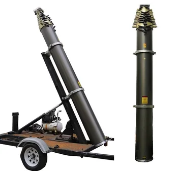
- Black And Gold Table Decorations
- 3/4 Watts Pressure Reducing Valve
- Flowclear 1000 Gal Sand Filter Pump
- Fridge Magnets For Pictures
- Temperature Laser Sensor
- How Thick Is Transparency Film
- Piedmont Plastics North Carolina
- Rio Brands Big Kahuna Beach Chair With Foot Rest
- Muddy Tripod Stand Walmart
- Best Contemporary Outdoor Wall Lights
- Multiples Clothing Spring 2022
- Finest Punta Cana Airport Transfer
- Metal Heat Press Machine
- On Running Nordstrom Rack


hydraulic telescopic mast
You must be concrete block molds for sale to post a comment.