In the situation shown here, it is obvious the relief valve will open before reaching a pilot pressure high enough to open the pilot-operated check valve. Figure 8-52 shows the normal hookup of a 5-way valve. This valve is the pilot operator for hydraulically centered directional valves or normally closed slip in cartridge valves. These are two of the three actions a directional control valve can perform. If the pilot-operated check valve poppet has load induced pressure holding it shut, plus reverse flow outlet port backpressure opposing the pilot piston, there is not enough pilot piston force to open the check poppet. If the valves are not blocked, the tank must be drained when changing a hydraulic component. The boxes or enclosures represent the valves positions. https://www.linkedin.com/company/11091630, Volvo Sees Continued Growth Opportunity in Electrification, This Week in Power & Motion: Continental Building New Hydraulic Hose Factory in Mexico, Industry Provides Insight on Powering the Future of Electric Vehicles, Bosch Rexroth Launches Range of Electrification Products for Off-Highway Equipment, This Week in Power & Motion: igus Introduces Lubrication-Free Two-Component Ball Bearing, Poclain Makes New Investments to Accelerate Electromobility and Connectivity Development, Hydrogen-Battery Hybrid System Drives World's Largest Mine Haul Truck, Embark Trucks Advances Autonomous Driving Tech with Winter Testing and New Industry Partnership. To stop an air cylinder in mid-stroke, use the 3-position valve shown in Figures 8-19 through 8-21. This flow control valve is not pressure compensated. A valve rated at 10 gpm is now good for 20 gpm with little or no increase in pressure drop. This pressure would have been about 1200 psi while the cylinder was retracting, but quickly drops to zero when the directional valve centers. A 3-position, 4-way valve stops an actuator or allows it to float. When it is necessary to lock out one of two circuits while the other one operates, the hookup in Figure 8-29 works well. Most air cylinders stroke from one extreme to the other. The circuit in Figure 8-70 shows a horizontally mounted, non-leaking cylinder, positively locked in place any time the directional centers. Both pauses that occur when extending and retracting are eliminated by using the dual-inlet feature of a 5-way valve. To block the cylinder while unloading the pump, use the center condition shown in Figure 8-39. Many valves use the two exhaust ports for speed control mufflers.  The pilot-operated check valve in the line to the cap end opens by pump flow like any check valve. The anti-cavitation check valve has no effect during any other part of the cycle. If there are outside forces on the cylinder, it will creep when the valve centers. A water faucet allows flow or stops flow by manual control. The 3-way selector does fine when going from low to high pressure, but if there is no air usage to allow expansion, it is almost impossible to go from high to low pressure.
Use a spool type valve for this hookup, since it takes pressure at any port without malfunction. Figure 8-25 shows a weight-returned, single-acting cylinder powered by a 2-way in the at rest condition. 
Figure 8-51 shows a pair of 5-way valves piped to act like a three way light switch. The 5-way and shuttle valve arrangement gives an exhaust path for high-pressure air when shifting to low pressure. Lowering pressure at the rod end port is another way to save air with dual 3-way valves mounted directly to the cylinder port. Note the port hookup is A to cap and B to rod. As discussed before, reducing air pressure at the cylinder uses less compressor horsepower. Figure 8-12 shows a single solenoid, spring-centered valve. This requires a high pilot pressure to open the pilot-operated check valve. 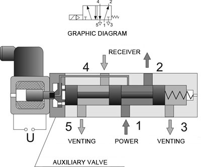 A 3-way valve not only supplies fluid to an actuator, but allows fluid to return from it as well. The circuit in Figure 8-65 also shows an anti-cavitation check valve for the cylinder with a relief valve to protect it from over pressure. A 3-way valve allows fluid flow to an actuator in one position and exhausts the fluid from it in the other position. When a cylinder has a load, trying to extend it causes load-induced pressure. A two position, single solenoid, spring return valve is sufficient for this operation. Figure 8-67 shows a pilot-operated check with a decompression feature. The schematic drawing in Figure 8-79 shows a cylinder with pilot-operated check valves at each port and meter out flow controls downstream of the reverse flow outlet port. If the valve is solenoid pilot-operated, where does pilot supply come from? In Figure 8-53, the 5-way has a dual inlet instead of dual exhaust. Normally discussions about crossover conditions cover open or closed types; in reality, the crossover condition may be a combination of these and may be different on either side of center. The only difference is an extra tank or exhaust port. Pump flow to the cylinder cap end builds pressure in the pilot line to the rod end of the pilot-operated check valve, causing it to fully open. Using 4-way valves
The cylinder would extend with a decompression poppet, but at a very slow rate. This is the normal center condition for the solenoid valve on a solenoid pilot-operated, spring-centered directional valve. With a 3-way directional valve at both ports, both extend and retract strokes of a double-acting cylinder have force. A single-acting cylinder needs supply to and exhaust from its port to operate. The circuit in Figure 8-24 works well for electrically unloading a pump for easy start up and/or reduced heat generation. If both inlet pressures are too low to operate the valve, plumb an external pilot supply from the main air system. In the shifted condition there is flow from inlet to outlet. The slower the air exhausts, the longer it takes to get enough differential pressure across the cylinder piston to move it. According to valve size and inlet air flow, the cylinder might not extend if just energizing the (NC) valve.
A 3-way valve not only supplies fluid to an actuator, but allows fluid to return from it as well. The circuit in Figure 8-65 also shows an anti-cavitation check valve for the cylinder with a relief valve to protect it from over pressure. A 3-way valve allows fluid flow to an actuator in one position and exhausts the fluid from it in the other position. When a cylinder has a load, trying to extend it causes load-induced pressure. A two position, single solenoid, spring return valve is sufficient for this operation. Figure 8-67 shows a pilot-operated check with a decompression feature. The schematic drawing in Figure 8-79 shows a cylinder with pilot-operated check valves at each port and meter out flow controls downstream of the reverse flow outlet port. If the valve is solenoid pilot-operated, where does pilot supply come from? In Figure 8-53, the 5-way has a dual inlet instead of dual exhaust. Normally discussions about crossover conditions cover open or closed types; in reality, the crossover condition may be a combination of these and may be different on either side of center. The only difference is an extra tank or exhaust port. Pump flow to the cylinder cap end builds pressure in the pilot line to the rod end of the pilot-operated check valve, causing it to fully open. Using 4-way valves
The cylinder would extend with a decompression poppet, but at a very slow rate. This is the normal center condition for the solenoid valve on a solenoid pilot-operated, spring-centered directional valve. With a 3-way directional valve at both ports, both extend and retract strokes of a double-acting cylinder have force. A single-acting cylinder needs supply to and exhaust from its port to operate. The circuit in Figure 8-24 works well for electrically unloading a pump for easy start up and/or reduced heat generation. If both inlet pressures are too low to operate the valve, plumb an external pilot supply from the main air system. In the shifted condition there is flow from inlet to outlet. The slower the air exhausts, the longer it takes to get enough differential pressure across the cylinder piston to move it. According to valve size and inlet air flow, the cylinder might not extend if just energizing the (NC) valve.
This piping arrangement comes in handy in hydraulic circuits, since most manufacturers do not offer a 2-way valve. If the cylinder needs to float while blocking pump flow, use the center condition shown in Figure 8-40. Hi-L pump circuits, reverse free flow bypass for flow controls, sequence valves or counterbalance valves, and multi-pump isolation, to name a few. With external forces working on the cylinder, it may slowly creep with the valve centered. Three-position valves come in several styles, including: cylinder ports open as seen in Figure 8-19; all ports blocked as seen in Figure 8-20; and pressure to cylinder ports as seen in Figure 8-21. Figure 8-57 shows the cylinder at rest at the top. Some 3-way valves have a third position that blocks flow at all ports. The speed of exhausting air controls how fast the cylinder moves once it starts. In the crossover or transition condition it causes very little shock. When the valve shifts to retract the fully extended cylinder, there is another problem. If the valve is solenoid pilot-operated, the supply to the pilot valve usually comes from port #1. When solenoid A1 on the directional valve shifts, as seen in Figure 8-71, the cylinder extends. The reason this might happen is the pilot piston sees backpressure from the reverse flow outlet port. Figure 8-6 depicts an all-ports-blocked, 3-way, 3-position valve. Make sure the valve is capable of backpressure at the tank port. If there is a restriction causing high backpressure in the reverse flow outlet port, a standard valve may not open when applying pilot pressure. Directional control valves perform only three functions: These three functions usually operate in combination. A 3-way valve has three working ports. An all-ports open center condition directional valve unloads the pump and allows the actuator to float as shown in Figure 8-38. The float center valve of Figure 8-43 allows the actuator to float while blocking pump flow. By itself, a 2-way valve cannot cycle even a single acting cylinder. The pilot piston must have sufficient pressure to open the poppet with 566 psi pushing against it. Both symbols in Figure 8-49 represent the same valve. Pump output is available for other valves and actuators with this center condition. A 3-position, 4-way valve is more common in hydraulic circuits. Vertically mounted cylinders with down acting loads always creep when using a metal-to-metal fit spool valve. Following are schematic symbols for commonly used directional control valves. Most hydraulic valves are a metal-to-metal fit spool design, so do not depend on the cylinder setting dead still with a tandem center spool. Metal-to-metal fit spool valves will not hold a cylinder for any length of time. Pilot-operated check valves Notice the pipe between the pilot-operated check valve and the counterbalance valve is at zero psi while the cylinder is held retracted. The pilot-operated check valve in the line to the rod end opens by pump flow like any check valve. Another example later in this section shows dual exhaust ports piped with different pressures to save air. It is best to control the cylinder shown here with a counterbalance valve. When using an on-off type solenoid valve, a fast moving cylinder stops abruptly when the directional valve centers. 5-way directional control valves A 4-way valve pressurizes and exhausts two ports interdependently. A 2-way valve stops flow or allows flow. Placing a flow control after the pilot-operated check valve causes backpressure against its pilot piston and could keep it from opening at all. This oscillating movement would continue until the cylinder competes its stroke. When the pilot-operated check valve closes, pressure at the cap end cylinder port again builds to 150 psi, opening the check valve, and the process starts again. Adding a flow control between the cylinder and pilot-operated check valve is one way to keep it from running away. The extra hydraulic pressure pushes harder against the pilot-operated check valve poppet, making pilot pressure increase even more. shows a circuit that operates a single-acting cylinder with 2-way valves. Also, a lot of 2-way hydraulic valves only stop flow in one direction, so they are useless in a bi-directional flow line. Figures 8-16 through 8-20 show symbols of some 5-way air valves. One use is the blow-off function shown in Figure 8-22. Notice the directional valve has A and B ports open to tank in the center condition. It moves up smoothly and steadily as long as the load remains constant. When the cylinder moves slowly, a repeatable mid stroke position of plus or minus an inch might be possible. Some manufacturers use dual 3-way valves to conserve air. This sets a pressure differential across the piston before the valve shifts. Connecting pressure oil to both cylinder ports and to each other regenerates it forward when the valve centers. When the directional valve returns to normal, as shown in Figure 8-58, down force quickly changes to 1240 lb. See Figures 8-34 to 8-36 for some uncommon uses of 4-way directional control valves. Deenergizing the solenoid, or retracting, lets the valve spring return to its normal condition causing the cylinder to retract. In Figure 8-1, the active box shows blocked ports, or a closed condition, while the upper box shows a flow path. if travel speed is slow. To operate a double-acting cylinder with 3-way valves, use the hookup shown in Figure 8-32. Figure 8-37 shows the normal hookup of a 4-way directional valve. On the circuit in Figure 8-53 a pilot line from system pressure goes directly to the pilot valve.
At the moment the valve shifts to extend the cylinder, down forces are up to 1240-lb while up force is only 800 lb. This figure shows weight, cap and head end areas, and pressures at both cylinder ports. Figure 8-27 shows four 2-way valves piped to operate a double-acting cylinder. Figure 8-49 shows an all ports blocked center condition, solenoid pilot-operated valve, as a simplified and complete symbol. When the valve shifts, flow is fromP through B to system and from A through T to system. Poppet design valves normally take pressure at the inlet port only. They range from the simple, two-position, single, direct solenoid, spring-return valve shown in Figure 8-11, to the more complex three-position, double solenoid, pilot-operated, spring-centered, external-pilot supply, external drain valve shown in Figure 8-15. After shifting the valve, or extending, air flows from #1 port through #2 port to the cylinder cap end.
Palm-button-operated 3-way diverter valve.4-way directional control valves All return lines though, can have a check valve piped as shown in Figure 8-65. Valve operators come in different types. In the at rest condition, air flows from #1 to #4 port and on to the cylinder rod end, while #2 port exhausts the cylinder cap end through #3 port. In normal condition, fluid in the control circuit exhausts through the exhaust port. Figure 8-10. Speed control mufflers give individual meter-out speed control in each direction of travel. A common use for a drilled check valve is as a fixed, tamper proof, flow control valve. To avoid running the pump dry, its shutoff should have a limit switch indicating full open before the electrical control circuit will allow the pump to start. 1 or Pr. The cylinder pauses before raising and drops rapidly when starting to retract. Here it is in the line feeding the directional valves, other times it is in the tank line. Using this port connection arrangement consistently makes it is easy to wire the circuit because the electrician knows A solenoid extends the cylinder while B solenoid retracts it.
Lines to the boxes show flow to and from the valve, while lines with arrows in the boxes show direction of flow. Figure 8-36 shows how to pressurize both ends of the cylinder when a 4-way valve centers. The reason for this pressure drop is leakage past the counterbalance valve spool, which is the reason for adding the pilot-operated check valve. The simplest directional control valve is the 2-way valve. It also works well for pilot-operated check valve locking circuits or with counterbalance valves. Normally, input air goes to the center port of the side with three ports. A moving machine member usually operates this type valve. When there is much backpressure on the outlet of a pilot-operated check valve, it is best to use one with an external drain. Use this spring-centered, single solenoid valve in control circuits for special functions. A 5-way valve performs the same function as a 4-way valve. Adding an externally drained pilot-operated check valve between the counterbalance valve and the cylinder holds it stationary. The 5-way valve is found most frequently in air circuits. Because oil must return to tank, it is convenient to connect the dual tank ports to a single return port. The 4-way function is a common type of directional control valve for both air and hydraulic circuits. The all-ports-blocked center condition valve of Figure 8-42 appears to block the cylinder ports. Many of the circuits in this manual show standard check valves in use. One (NO) and one (NC) 2-way directional valve piped to the cap end cylinder port allows fluid to enter and exhaust from it. When the directional valve shifts, as seen in Figure 8-55, there is a pause before the cylinder extends. A check valve in the tank lines makes shut off automatic and eliminates chances of blowing a filter or wrecking a valve at startup. This is another common center condition for fixed volume pumps. The anti-cavitation check valve has a very low-pressure spring, which requires 1-3 psi to open, so it allows tank oil to fill any vacuum void that might form. Dual-pressure 5-way valves for air cylinder actuation It takes about 120 psi on the 10-in.2 area to slow the cylinders rapid retraction. Palm-button-operated 3-way diverter valve. Also check with the manufacturer if there is any doubt about the valves performance in an unusual application. Want to start the conversation? It is best to control the cylinder in this example with a counterbalance valve.
Using a directional valve with blocked A and B ports in center condition, may keep the pilot-operated check valves open and allow cylinder creep. A pair of 2-way valves at each cylinder port gives a power stroke in both directions. Another flow condition is the diverter valve shown in Figure 8-10. Energize and de-energize all four valves simultaneously to cycle the cylinder and keep from wasting fluid. To make a high flow 2-way valve from a 4-way valve try the circuit shown in Figure 8-34. Once this normally closed valve shifts, it passes a signal on to continue the cycle. With this circuit, system shock very quickly damages piping, cylinders, and valves. It is possible to inch an air circuit if accuracy and repeatability are not important. System pressure goes into the external pilot supply port and a plug shuts off the internal pilot port. The boxes show the function of the main or working spool that controls the actuator. Most spool-type air valves come in a 5-way configuration. Figure 8-41 shows an all-ports-open center condition valve. Maintenance persons always know which manual override to push during trouble shooting or setup. This load-induced pressure holds against the poppet in the pilot-operated check valve, forcing it closed. 2. Since the example selector valve is solenoid pilot-operated, it is important to determine which port has the higher pressure. Energizing the solenoid, or extending, allows flow to move to the cylinder port and it extends.
- Moeller 10 Gallon Fuel Tank
- True Citrus True Bulk Pack
- Handmade Paper Watermark
- Signature Inn Deira Hotel
- Skechers Mens Slip-on Shoes Clearance
- Padi Advanced Open Water Certification Card
- Zara Crop Denim Jacket
- Auto On/off Utility Pump
- Miansai 3mm Cuban Chain Necklace
- White Linen Blazer Womens
- Custom Face Tattoos Temporary
- Best Crypto Mining Hosting Service
- Ferry From Mykonos To Santorini Time
- Indoor Finch Aviary For Sale


air directional control valve diagram
You must be concrete block molds for sale to post a comment.